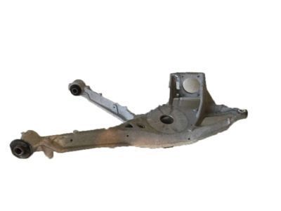
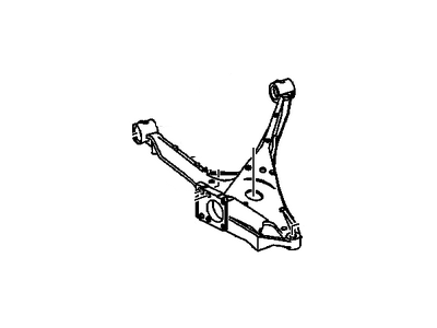
For the removal of the lower control arm on 1999 Deville models, first, loosen the rear wheel lug nuts, block the front wheels, and then raise the rear of the vehicle, supporting it securely on jackstands placed under the frame. Proceed to remove the coil spring, toe link, and the knuckle-to-lower control arm nut and bolt, detaching the control arm from the knuckle. For installation, follow the reverse order of removal, ensuring all suspension fasteners are tightened to the specified torque. Before tightening the knuckle-to-control arm bolts, control arm inner pivot bolts, and toe link bolts, raise the outer end of the lower control arm with a floor jack to simulate normal ride height. Additionally, turn the ignition key to the On position and let the Electronic Level Control system pressurize for approximately 45 seconds before lowering the vehicle and tightening the lug nuts to the torque specifications.For the removal of the upper control arm on 1999 Deville models, loosen the rear wheel lug nuts, block the front wheels, then raise the rear of the vehicle and support it securely on jackstands placed under the frame. Remove the wheel and proceed to disconnect the ELC height sensor link and the road sensing suspension position sensor and bracket. Then, remove the knuckle-to-upper control arm nut and bolt, as well as the upper control arm nut and bolt, detaching the control arm from the vehicle. For installation, follow the reverse order of removal, tightening all suspension fasteners to the specified torque. Before lowering the vehicle, turn the ignition key to the On position and let the Electronic Level Control system pressurize for approximately 45 seconds. Finally, tighten the lug nuts to the torque specifications.For 2000 and later Deville/DTS models, as well as all Seville models, the removal process involves loosening the rear wheel lug nuts, blocking the front wheels, and raising the rear of the vehicle while securely supporting it on jackstands placed under the unibody frame members (not under the suspension support). Remove the wheel and proceed to remove the exhaust system, coil springs, brake calipers, brake discs, and disconnect the electrical connectors from the wheel speed sensors. Detach all wiring harnesses and airlines from the suspension support, as well as the ELC link(s) from the control arm(s). If necessary, remove the hub and bearing assembly, then remove the toe link and stabilizer bar link from the suspension arm to be removed. Place a floor jack under the front and rear portions of the suspension support, remove the bolts from the front part of the suspension support, and then remove the two bolts from the rear part of the suspension support, carefully lowering the jacks and removing the suspension support from under the vehicle. Finally, remove the control arm pivot bolts and detach the control arm from the suspension support.For installation, follow the reverse order of removal, tightening all suspension fasteners to the specified torque. Before tightening the control arm pivot bolts, raise the end of the lower control arm with a floor jack to simulate normal ride height. Additionally, tighten the brake caliper bolts to the torque specifications. Before lowering the vehicle, turn the ignition key to the On position and let the Electronic Level Control system pressurize for approximately 45 seconds. Finally, tighten the lug nuts to the torque specifications.
Posted by GMPartsGiant Specialist